Adding Rivco LED Mirrors to a Victory Cross Country Motorcycle
This document describes adding mirrors with built-in LEDs to a Victory Cross Country Tour. That may seem like a simple project, but it turned out to be fraught with unforseen mechanical and electrical hurdles. I think it likely that some of these problems apply to other late-model motorcycles, so if you're interested in this type of "farkle," read on.
WHAT AM I TALKING ABOUT?:
There are several aftermarket vendors that manufacture replacement motorcycle mirrors that have one or two LED lights contained in each mirror or mirror housing. These additional lights can function as extra turn signals or running lights, or even serve as the only front- or rear-facing turn signals and running lights if you're building a custom bike or stripping down a stock motorcycle. Being hide and wide, mirror-based lights add an extra level of conspicuity — they're a significant safety farkle. Drivers hovering alongside and slightly ahead of your rear turn signals, for instance, should be able to see mirror-based turn signals.
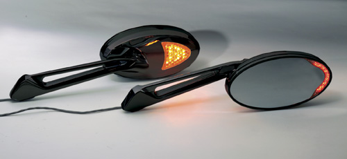
In my case, I added Rivco LED Lighted Turn Signal Mirrors - Black (part # MIRLEDBK, $249.95) to my 2012 Victory Cross Country Tour motorcycle. Rivco also makes a chrome version (part # MIRLED) for the same price. Here's a picture from Rivco's web site (hey, I'm giving them free publicity, so I assert that this constitutes "fair use"). As with all the pictures on this page, click on the image to enlarge it, and then press Escape or the "X" (which appears if you hover your mouse over it) to close the enlargement:

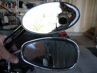
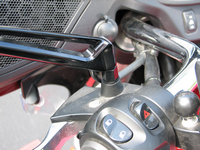
These mirrors have a red LED crescent curving around the outside edge of the glass in the mirror housing, rear-facing only. These are lit up only when the turn signals are activated. The front of each housing has a larger amber LED area. These are on all the time, as front-facing running lights, except that they will instead blink, along with the red ones, when the respective turn signal is active.
Rivco's web site states:
Installation is as simple as bolting them on and connecting three wires.
It also originally (when I was undertaking this project, back in 2013) stated:
This item will not work on Victory Crossroads or Cross Country models as the factory wiring will not allow the addition of extra lighting to turn signal circuits.
Update, September 2014:
That product page still states that you can't use these mirrors on a Victory. (Update, April 2016: that restriction has been removed by Rivco, who refers to its relay-based option.) However, contradicting that, the latest version of Rivco's instructions, released since I wrote this page, now include a second page, titled "Wiring diagram for MIRLED turn signal mirrors on late model BMW, Victory and others using CAN-BUS electrical systems." That new page shows you how to add two relays to make everything work as intended.
This is actually a similar approach to the one I took — and which I informed Rivco about, back then — but uses separate relays. As you'll see, using a trailer isolator is a way of using a pre-packaged collection of relays. I prefer my method, as it provides additional capabilities, should you need them for later work. Read on, please, as I discuss Rivco's approach in more depth later on.
Update, January 2018:
I recently noticed that Rivco now sells a product they call the MIR100 CAN Bus Module ($59.95). The wiring of this module, in conjunction with the Rivco mirrors, is included on the second page of Rivco's mirror instructions.
Given that the MIR100 product page specifically mentions Victorys (among some other brands), I think this is the way to go now. That is, while I have no hands-on experience with the MIR100, if I were doing this mod today I would probably buy it, and see if it works. It is a less expensive form of the particular isolator I bought, and we seem to have Rivco's word that it would do the job.
I read that first quote a long time ago. I don't know whether I got tired of reading then, or whether the second quote was added much more recently to Rivco's web page. In any event, I didn't read Rivco's caveat about Victory bikes until after I started this project, when it was pointed out to me (thanks, Mark).
So, I personally discovered that:
-
Rivco is correct: if installed in a typical manner, you get strange, unwanted, results (as I describe later on).
-
You can get these mirrors to work just fine on a Victory "Cross" bike, but you'll need to add an extra electronic control.
-
You'll also need to do some minor fabrication work, in order to mount the right-side mirror.
-
I suspect that you'll face similar electrical issues with a lot of modern bikes, especially those with CANbus wiring systems (such as most, if not all, late-model BMWs).
I'll detail these additional requirements in a moment. First, however, some background information is in order.
THE OTHER MIRROR CANDIDATES:
In addition to Rivco, a few other companies make turn signals with LEDs:
-
Muth makes Motorcycle Signal Mirror Kits. Muth is an OEM supplier to some car companies, and their arrow formation of LEDs behind mirrored glass — visible only when lit — is a work of art. I installed a set of these on my 2000 Honda Valkyrie Interstate. These were bright and classy, and had one feature often overlooked by other designers (including, as we'll see, Rivco): there was a set screw on the mirror housing that allowed the tension to be adjusted in the ball-and-socket housing pivot area.
But there are a few drawbacks to the Muth product. First, at $469, plus possibly another $25 for thread adapters, they're almost twice as expensive as the Rivcos. Next, the version I installed in 2003 had only the rear-facing LEDs, i.e., they did not have forward-facing LEDs to function as running lights; at least this deficiency has been corrected now — see Muth's METRIC CRUISER page. Last, the wiring that ran from the mirrors down the stalks was not fully enclosed, which is something that I'd expect for $400+. (This is not an issue if you're using Muth's replacement-glass-only models for bikes that have enclosed mirror housings built into their bodywork, such as Gold Wings, some BMWs, and Victory's Vision.)
Update, October 2015:
Muth recently came out with a product called Merge Master Signal® Mirrors. A pair of these costs $204.00 (including the thread adapters — I'm not sure if they're required for the Cross Country). That is significantly cheaper than Muth's other stem-mounted mirrors, and even cheaper than the Rivco mirrors. When I emailed Muth, asking about the pricing, I was told: "The Merge Masters are less expensive because they aren't machined from billet. They are die cast in higher volume. However, they have gone through the same rigorous testing as our Billet mirrors."
Like the Rivcos, the Merge Masters have forward-facing LEDs, in addition to embedded rear-facing turn signals. And like the Rivcos, they are available in chrome or black. Had the Merge Masters been available when I was shopping for LED mirrors, they certainly would have been serious contenders.
-
Kuryakyn makes two products, Blind Spot II Turn Signal Mirrors (part # 1499, $193.99, plus adapters, part # 1411 or part # 1413, $10.99) and Turn Signal Mirrors (part # 1432, $203.99, plus adapters, part # 1411 or part # 1413, $10.99).
Each of the Blind Spot II Turn Signal Mirrors has "an L.E.D. Amber turn signal directed to the side," i.e., a single, edge-mounted, LED area. Thus, no running-light function. I will say that if you're really interested in running lights — and I think that you should be, especially if your bike doesn't have them in the front — there are several companies that make electronic gizmos that add this capability to stock turn signals (although they, too, are not likely to work on Victory "Cross" bikes).
Kuryakyn's Turn Signal Mirrors look a lot like the Rivcos, actually, but the forward-facing LED area on them is all you get; they function as both a running light and turn signal, but the turn signal is a forward-facing one. So, if you're interested in these mirrors, in terms of adding turn signals you have to ask yourself whether you want to garner more attention from motorists in front of you — these Kuryakyn mirrors — or both in front of and behind you — the Rivco mirrors.
-
As pointed out to me (thanks, Kevin) in this VOG.net thread, Chrome Glow sells Oval LED Turn Signal Motorcycle Mirrors for $190.95 (plus the cost of stalk-thread adapters). These look to be the equivalent of the Rivco mirrors — front and rear LEDs for signals, and forward-facing running-light LEDs — and about $60 less costly. This is another alternative, although Chrome Glow notes (in the FEATURES tab) that the "Red mirror side LEDs notifies when signal is left on by mistake (not intended visible by drivers behind you)" and also that they are "Not recommended for bikes with heavy vibration ( ex. Aftermarket exhaust, Engine upgrades, hard tails)."
There may, of course, be other LED-mirror vendors, but if so they've escaped my notice.
I decided on the Rivcos because I wanted forward-facing running lights — the Victory has nice bright LED turn signals, front and rear, but no front running lights — and I felt it important to add high-mounted turn signals that are visible to traffic approaching from the rear (which may be in your lane, or alongside) or from the front (in which case, hopefully, traffic isn't in your lane). And I didn't want to be bothered with additional electronic add-ons that convert turn signals to running lights (which may or may not work); as we'll see, this project became complex enough.
PHYSICAL INSTALLATION OF THE RIVCOS — PIVOT POSITIONING:
You physically install the LED mirrors before doing any electrical hookups. This process is straight-forward, but there are a couple of "gotchas" that you have to be aware of.
Rivco's instructions tell you:
Lay the mirrors out: notice that one of the heads is upside down from [i.e., as a result of] the way it is packaged. Rotate this mirror ahead to be right side up so that the lettering is at the bottom of both mirrors.
This is the first gotcha. Like almost all mirrors, the mirror housing rotates on the mirror stalk by way of a ball-and-socket arrangement. In the case of the Rivcos, you might think that the housing is welded to the ball. Sifting through the Internet to make sure that this recalcitrance was not some sort of a fluke, I came across this more colorful (if PG13-rated) description on a Triumph forum: "The mirrors adjustment was stiffer than a 19 year old's pecker."
Enlisting the aid of a friend, with one of us holding the stalk and the other grasping the outside of the housing, didn't help; we gave up, fearful of breaking that mirror. Our Plan B: we sprayed some PB Blaster around the ball, and let it soak in for a while; we were then able to un-freeze that mirror, but it still required the use of the buddy system. Next, we sprayed some silicone lubricant in that area, and let that soak in for an even longer period.
The ball-and-socket now works slightly better than before. While I can appreciate Rivco's concern that your set positioning stays put even on, say, a Harley at idle, I still wish for the tension-setting screw found on the Muth mirrors that I installed a decade ago. Incidentally, I sent e-mail to Rivco, asking for their suggestions on this issue; I'll let you know if they ever get back to me.
PHYSICAL INSTALLATION OF THE RIVCOS — STALK THREADING:
Remove each stock Victory mirror by simply loosening the nut at the bottom of the stalk (with a 17mm wrench), and then unscrew the stalk. Both of these are standard threads, i.e., "lefty-loosey."
Rivco nicely provides three adapters for "metric" bikes, and a couple of bolts and washers for H-Ds. One of the adapters has a groove running circumferentially around the outside of its large nut; this is a reverse-threaded adapter, apparently for the right-side mirror on some Yamaha models. We'll ignore all of that, and use the other two adapters.
Put some red thread-locker on the smaller end of each adapter — and only that end — and screw them solidly into the bottom of the stalks (using a 10mm wrench, despite the instructions' note of an 8mm one). Let the thread-locker set.
What normally comes next is this:
-
By hand, turn the large nut on each adapter such that it is resting against the stalk proper, i.e., expose the maximum amount of threads on the large, bottom, portion of the adapter.
-
By hand, screw the bottom of each adapter into the bike, holding the wiring up along the stalk, so that it doesn't get twisted.
-
When you reach the end, the stalk probably won't be aligned such that it is sticking straight out (sideways) from the bike, so back off a revolution or less, such that the alignment is the way you like it.
-
Tighten down the large nut on the adapter (with a 14mm wrench), such that the stalk is positioned to your liking. Since you'll still have to adjust the mirrors via the ball-and-socket mechanism, my suggested torque value for this stem nut is "very tight."
-
Route the wiring along the handlebars with existing bundles, and feed the ends into the fairing area. You'll want to add two or three wire ties on each side; leave some slack at the bottom of the stalks (so that they can be slightly repositioned as time goes on, if need be), but make sure (adding a wire tie in the area) that the wires don't interfere with or can get pinched by the movements of the clutch and brake levers.
However, in the case of some Victory models — I don't know how many, but my Cross Country Tour is among them — and perhaps some other brands, there's another "gotcha."
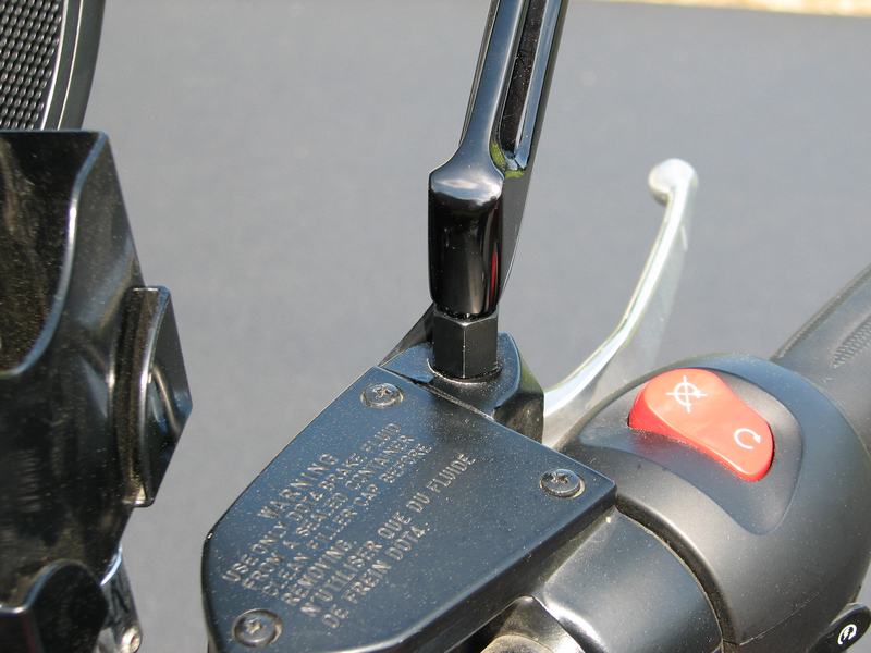
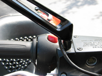
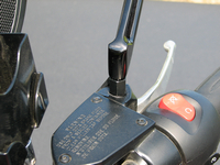
The problem is that the area that accepts the right-side mirror threads is recessed into a portion of the front brake reservoir housing (just to the right of the master cylinder cover). The stock locking nut flares into a conical section on top. What concerns us here, however, is that the bottom portion of this nut consists of a sort of sleeve; the nut on the Rivco-supplied adapter does not have this extra sleeve area (disregard the groove on the Rivco jam nut and the reverse threads on its adapter, discussed above):
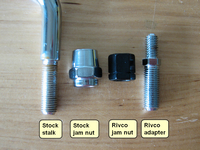
This sleeve area has an outside diameter of about 0.58" (15mm) and is about 0.16" (4mm) deep. If you were to just tighten down the nut on the Rivco adapter — as I was doing, before I noticed this problem — you'd wind up buggering the top surface of this area of the reservoir housing, and you would not be able to solidly lock in the stalk.
Here's what I did. I bought some washers at my local hardware store. It turns out that it's not hard to find them with an OD of 0.58"; depending on their thickness, one may suffice. I then drilled out the washer(s), using a series of bits, such that the threaded end of the stalk could pass through; the threads have an OD of about 0.39" (10mm). Doing this drilling was a PITA, because you will wind up not having much material left in the washer; if you clamp it on edge in a vise with much force, you'll wind up bending it. Last, I also bought a pretty hard neoprene (or something like that) black washer, with an OD of about 0.63" (16mm); this covered up the metal washer, and the buggered area on the cover, and still allowed me to rigidly tighten the adapter nut.
Another possible solution, had I known of this problem beforehand, would be to order a stock black mirror jam nut. For the 2013 model year, Victory came out with some blacked-out versions of the Cross Country, which come with black mirror stalks and housings. I have not verified this, but I believe what you need is part number 7547397-266, "NUT, JAM, MIRROR, BLACK"; this goes for about $5, if you shop around.
However, if instead of drilling out washers, etc., you use the very large stock nut on the right side (either in chrome or black, for either the chrome or black Rivco version), you'll wind up with — um, how shall I say this? — a mismatched set of nuts. And I think that will look pretty bad, much worse, for instance, than the mismatched stalk heights already present on the Cross Country.
Note that you don't need to go through any of these machinations on the left side. The left mirror mounts in a special-purpose raised area of the clutch-lever holder, which is, thankfully, flat metal on top, i.e., not recessed. In fact, although I haven't tested this, it looks as if you can't use the stock nut on the left side. Because the left side does not mount in a recessed thread area, and because the conical top of the stock nut does not fit around the bottom of the Rivco stalk (the way it does on the stock stalk), I don't believe you'll have enough threads left on the supplied adapter, i.e., it's not long enough. Thus, I believe you have to use the Rivco nut on the Rivco adapter on the left side.
Another possible solution regarding the recessed thread area, when adding either the black or chrome version of the Rivco mirrors, presents itself if you happen to have installed Victory's optional hydraulic clutch kit. In that case I think you can use a pair of the chrome or blacked-out Victory jam nuts (although I've never actually seen this optional clutch housing).
While I suppose Rivco can't cover all eventualities, what they should do is include a nut that's fashioned such that it incorporates a bottom sleeved area, if they want to make it easy for Victory owners. Or maybe just provide seperate, appropriately sized, sleeves (in chrome or black, to match the jam nuts they supply).
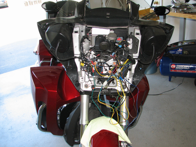
TAKE OFF THE FAIRING:
You need to remove the fairing to get at the wiring, but this is not a major undertaking. Here's a PDF copy of the two pages from the Victory shop manual that cover that process (again, I'm relying on the "fair use" doctrine of copyright law): pages 3.14–3.15.
Here's the drill:
-
If you have the tall windshield that's stock on the XCT, remove it (six bolts, but the brackets can stay in place).
-
Remove the headlight trim ring.
-
Remove the four headlight 5mm bolts. (Ignore the two Phillips screws; they adjust the aim.)
-
Swing the headlight down a bit, and lift out. Holding the headlight, disconnect the two headlight wires. If your model doesn't have an HID bulb, these connectors will be similar; note which goes where. Even if you do have an HID bulb, the other connector will be lurking around inside the fairing, disconnected; don't mistakenly use that connector when reconnecting the halogen high beam.
-
Disconnect the turn-signals wires. If you raise the edge of the bike-side connector (with a tiny screw driver, for instance) in order to disconnect it, do so very slightly, in order not to break that piece of plastic.
-
Remove the speaker grills, prying up the outside edge (as the inside edge has L-shaped tabs).
-
Remove the four 4mm screws on each side: one by the outside of the speaker area, and three down the outside edge (two of which will be longer, if you have the fairing winglets on your model).
-
Swing the fairing out and up from the bottom a bit, and then lift the top up and back.
Once you've done this a few times, the entire process takes right around ten minutes. Really.
Reassembly is the reverse. The only caution needed is not to pinch the headlight and turn-signals wires when you put the fairing back on. The fairing itself has two large L-hook latches built into the top, four large and four small alignment protuberances along the edges, and a single nipple below the headlight for bottom alignment. Just line things up, and push; make sure that the built-in latching areas snap in place, both along the top and along the lower sides.
If you haven't done this before and if you have a Harbor Freight store near you, I recommend their 4 Piece Nylon Pry Bar Installer Kit (or equivalent, from most auto-parts stores):
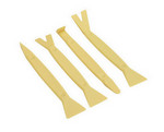
Having something like this makes removing the speaker grills and headlight trim ring a snap; the set is cheap (you can use any one of the four), and the pry edges are hard and thin enough to get the job done, yet soft enough not to scratch or mar anything.
You'll also need some hex keys. For the four (5mm) bolts that hold the headlight in place, you'll probably need a ratchet, but for all the other (4mm) bolts, a short extension and a thumbwheel should do the trick, i.e.:
Incidentally, if you've added Madstad brackets and windshield (as I have), there's no need to remove it; tilting the windshield back all the way will provide enough clearance.
RECOMMENDATIONS OF ELECTRICAL CONNECTORS AND TOOLS:
Since you'll be looking at pictures of connectors, you should know what you're looking at, and why. If you're already an expert at connecting wires, feel free to skip this section.
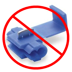
When you "tap" into an existing wire, you can actually tap into it, using, for instance, 3M Scotchlok Connectors or imitations of them. They look like this:

These simply don't make a reliable, trouble-free, connection. You'll see, below, that some of these were provided with the Electrical Connection wire harness, but I didn't use them.
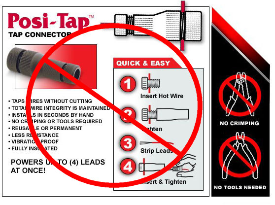
You could also use a Posi-Tap™:
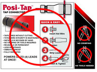
These are much better than the Scotchlok type of connectors. However, I've added some electrical farkles using Posi-Taps, and in my experience these do not make reliable connections, either. Yes, I used the correct sizes for the wire gauges I was using. Also, if you're just experimenting, you need to be aware that if you remove a Posi-Tap, you're left with a tiny puncture in the insulation. A lot of folks swear by Posi-Taps, but I'm not one of them.
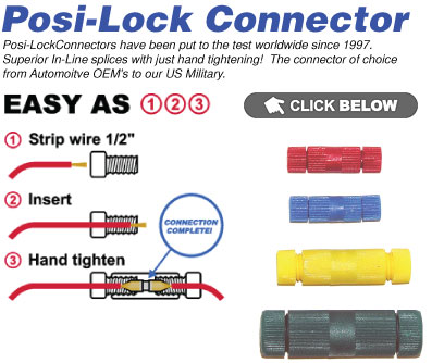
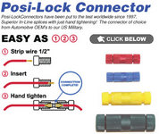
What do I use? Two products: Wago Cage Clamp® Compact Connectors and Posi-Lock™ Connectors:
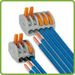
For "tapping" into an existing wire, I cut that wire, and then insert those two cut ends, along with the wire to be added, into a three-connector Wago. If you're adding several wires to an existing one, simply use the five-connector version.
Each wire end needs to be stripped, and the length of insulation to be removed is shown by a physical indentation on the back of the Wago. And that's it: flip open a lever at a wire position, insert the wire, and close the lever. These connections are snug and stay put, and accommodate all the wire sizes you'll be using (short of a 10-gauge connection to a battery). And if you want to re-do or un-do some work, simply flip open the lever and slide out a wire, which is completely undamaged.
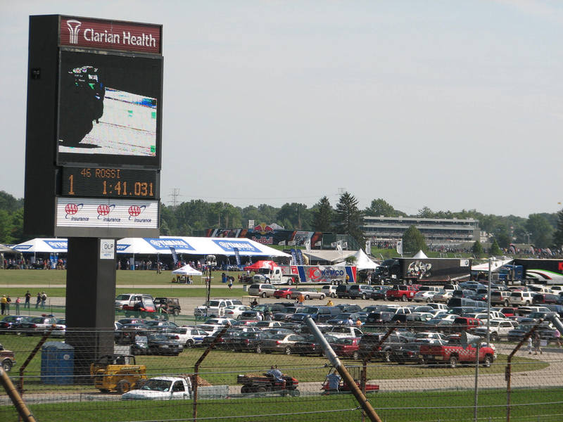
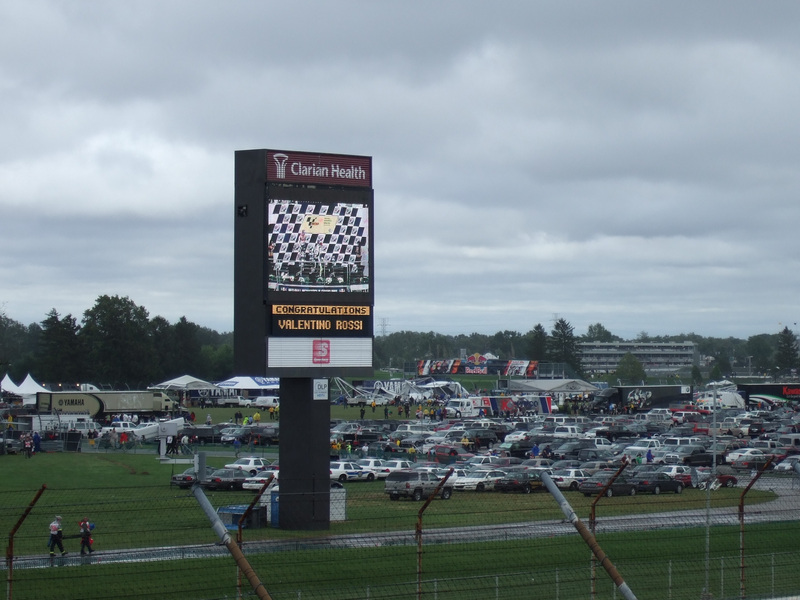
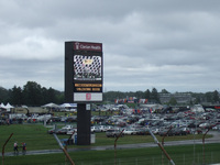
While these aren't waterproof connectors, I've been using these for years under bodywork without incident. This includes extensive use of three- and five-wire connectors on my 2007 Burgman 650 Exec, which was parked outside at the Indianapolis MotoGP in 2008. The event was subjected to the remnants of Hurricane Ike, with winds and rain strong enough to cancel one of the races, shorten another, and take down most of the Yamaha tent:

Among other places, you can buy Wagos in small quantities at Custom Dynamics, a store familiar to many motorcyclists. You can also get them in bulk (recommended) at Amazon, for instance. Highly recommended.
The Posi-Locks are made by the same company that makes Posi-Taps; while I don't use the latter, I'm one of the folks who swear by the former. To use these, you unscrew the end connectors, pass a wire — with some insulation stripped off the end — through that end cap and up against the inside of the central body of the connector, and screw down the end cap. For connecting two wire ends together, this forms a connection that may be stronger than a plain wire itself.
Like the Wagos, once connected the Posi-Locks stay put, and the wires are also left undamaged if you want to reverse this process to un-do a connection. Also like the Wagos, Posi-Locks are not technically waterproof (although the company does make versions that are); however, unless you submerge your bike — in which case you'll have more problems than this — you won't have to worry about water.
You can buy Posi-Locks at many places, including some NAPA stores. On-line providers include webBikeWorld, which has an extensive variety for sale (and for which I've written a dozen articles), and also at Custom Dynamics.
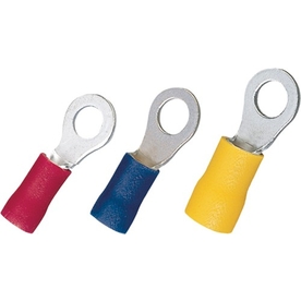
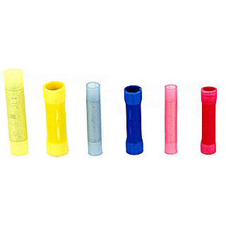
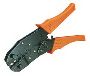
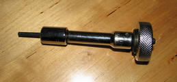
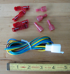
We'll also be using ring terminals — essential for battery hook-ups — and possibly a butt connector:


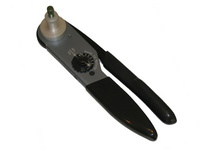
To make reliable connections using these types of connectors, you should use a ratcheting crimper. These have multiple jaws for different wire and connector sizes, and close securely on the connectors; they won't open until you've closed them sufficiently. I bought this Paladin model eight years ago (when it was much cheaper than it is now), but there are many other companies that make similar products, both more and less expensive:

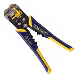
Speaking of tools, if you're still using some basic wire stripper that looks like a pair of scissors, you should upgrade to something such as the Irwin® Self-Adjusting Wire Stripper:

I use something very similar that's 30+ years old, and these tools save a lot of work, do a great job, and don't needlessly tug on wires.
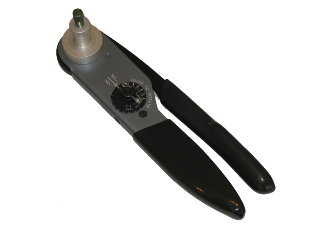
There are all sorts of other, much fancier, connectors. If you're very conscientious (or anal) and you want to emulate or even surpass a factory wiring harness and its connectors, you could use Deutsch connectors and the Deutsch crimping tool that retails for about $250 (and provides eight simultaneous "mil-spec" crimps, squishing a cylindrical connector onto a wire, as opposed to the typical two-sided crimps of the Paladin, et al.):
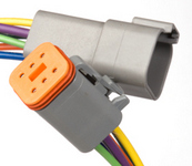
If you intend to add electrical goodies to many bikes to come, and you can afford the Deutsch connectors and crimpers, I think this is actually a reasonable purchase; there are similar connectors available from other vendors, but I think these are the best. Note that these sorts of connectors and tools are certainly not necessary for this project.
WIRING THE RIVCO LED MIRRORS — WHAT WON'T WORK:
Ten years ago, when I hooked up those Muth LED mirrors to my Valkyrie, I got power and ground from each of the stock front turn signal wires, and that was that. It just plain worked, and didn't even alter the flash rate (which I timed, before and after).
But times have changed. The Valk used incandescent bulbs, and had one of those old automotive-style flasher units. The Victory, on the other hand, uses LEDs all around for turn signals (and for the brake and running lights out back, too), and the flashing is just one of the many functions at least moderated by the electronic control module (ECM).
My first attempt at hooking up the Rivco LED mirrors duplicated that process: use the respective stock front turn signals for power and ground to the mirrors, as well. (Recall, the Rivcos have a running light function, too, but that's a separate connection, and is irrelevant to this part of our discussion. Consider it not hooked up, which for most of the time actually was the case.)
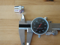
Victory nicely affixes labels to the left and right turn signal wires, the ones you disconnected as part of the fairing removal process. To determine which of each pair is the hot wire and which is the ground, all you have to do is switch on the ignition, flip the turn signal switch to the left or right, and insert a circuit tester into the end of the bike-side wires. A circuit tester, available at any auto-parts store, is just a light with a wire coming out one end (with an alligator clip) and a point at the other end. You attach the clip to the nearest big chunk of metal on the bike, and probe for voltage with the point:
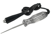
Just put the probe into one or the other open ends of the connector on each side, for a few seconds. If you've inserted the point into the ground wire, nothing will happen. If you've inserted it into the hot wire, the tester's light will flash, as if it were a turn signal; note the color of the wire that's going into the back side of that opening of the connector in question.
And don't disregard this live-wire determination step. I can't vouch for this, but according to reports on the usually reliable Internet, some Victorys came from the factory with the polarity reversed on the right-side front turn signal. If you hook up something backward, you run the risk of frying the ECM — which lists for something like $300 — which has also been a reported occurrence.
So what happened with the Rivcos on the Victory? Random acts of lightness.
With the left turn signal switch on:
-
Both the left mirror and the stock left-side turn signals functioned normally.
-
Every once in a while, however, only the mirror's turn signal worked. When that was the case, it would flash more quickly than normal.
With the right turn signal switch on:
-
Only the right mirror's turn signal worked (and would flash more quickly than normal).
-
Every once in a while, however, the right-side mirror and the stock front and rear signals would flash once; then, the stock signals would no longer flash, and the mirror would flash more quickly than normal.
With the four-way hazard flasher switch on:
-
Only the mirror turn signals would flash (and more quickly than normal); the four stock LEDs would not flash.
If I disconnected the Rivcos — a trifling matter, remember, because all I had to do was lift some levers on the Wago connectors and slide out two hot wires — the stock signals would return to normal, i.e., work fine.
OF EQUALIZERS ... :
Motorcycle-oriented "load equalizers" are resisters that you add in-line (i.e., in series) in a circuit. They are primarily designed to maintain the flash rate when you replace incandescent bulbs with LEDs. Custom Dynamics has a good selection of these, if you ever find yourself in need of some.
While I was not performing this classic case of substituting a high-resistance device with a low-resistance device, it's true that adding a device in parallel — which is what occurs when you tap into the existing turn-signal wires — lowers the resistance (as you'll recall from high school physics or other basic electricity class).
Nevertheless, I didn't opt to try any of these. Load equalizers may be appropriate in some circumstances, but they get hot, waste alternator capacity, and there's no guarantee that the load will be the value you need and that the ECM still won't find something to complain about.
... AND ISOLATORS:
What I did opt for was a trailer isolator. These are (usually) a grouping of solid-state relays, and are, yep, usually used for trailer wiring. This is the same concept you'd use when replacing the wimpy stock horn with a high-wattage air horn, for example: you use the existing horn wiring to trigger a relay, which then connects a new, separate, fused, circuit to the added horn ... which new circuit gets power from the battery, not from the existing horn circuit. This prevents blowing a small stock fuse, prevents overloading thin stock wires with too much current, and prevents sending more juice through the stock horn button than its internal contacts were intended to handle.
In the words of Electrical Connection (which apparently has some disdain for apostrophes), in a document that no longer appears to be on-line:
Trailer isolators easily and properly connect your trailers lighting while removing the electrical load from the motorcycles factory wiring, fuses, relays, computers and electronics.
You'll find similar explanations of how a trailer isolator functions on these Kriss and Rivco pages.
Most importantly (for our purposes), by using a trailer isolator, the minimal current drawn from stock hot wires — because that current functions only as relay triggers for our added LEDs — and the momentary nature of it — just the brief time to turn on or off a solid-state relay — does not throw the ECM into random hissy-fits with regard to the stock lighting. That is, we can run the mirror LEDs on power from the isolator, and the stock lights as before, and everyone now plays nicely together.
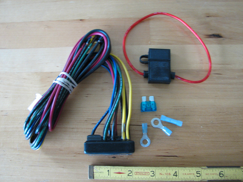
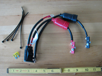
I purchased the Isolator, part # 07660, $69.95 (but now, April 2016, $79.95) and Universal Sub-Harness, part # 07663, $9.95, from Electrical Connection:
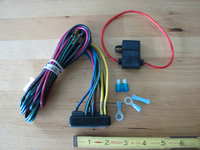
That corresponding harness from Electrical Connection is not technically necessary. You'll note that the isolator has pairs of matching-colored wires coming out of it. One of each (except the two blacks and the red) goes to a connector; the harness plugs into that, and those harness wires connect to stock-wiring sources that function as relay triggers. The other paired wires in the isolator — the ones that don't go into the connector — serve as power outputs; these wires are much thicker (14-gauge, I think). You could dispense with the harness, but then you'd have to be careful about which wire of each color is for what purpose, after cutting off the connector plug on the four isolator wires. It seems simpler to me just to spend the $10. Also, you can work with just the harness or the isolator, one at a time, when you're hooking things up; when you're all done, simply plug the two halves together.
By the way, if you stumbled upon this page and you don't have a Victory motorcycle, note that Electrical Connection also sells what appear to be plug-and-play isolators for some H-Ds, Hondas, and some other brands. See this page on that site.
OTHER TRAILER ISOLATOR CANDIDATES:
I've been purchasing odds and ends from Electrical Connection for about 15 years now, and I trust the quality of its products. If, however, you don't want to go with the Isolator from Electrical Connection, here are links to other trailer isolators I looked at:
(I was surprised that Eastern Beaver, another one of my favorite outfits for extremely high-quality electrical products, doesn't sell an isolator ... or if it does, I couldn't find it.)
RIVCO'S DUAL-RELAY APPROACH:
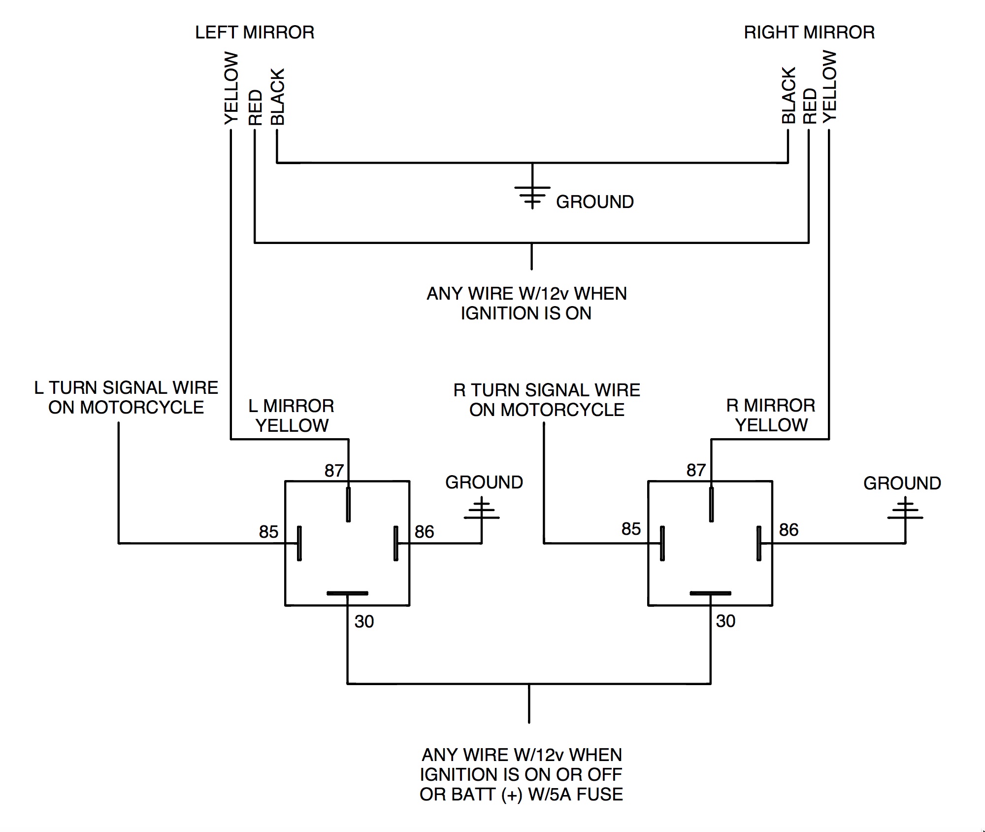
As I noted in the "Update, September 2014" near the start of this document, after I first wrote these instructions and pointed them out to the company, Rivco added a page to its installation instructions. Rivco no longer has that version of its instructions, but I did retain the relevant document for myself. The added page nicely describes the use of two garden-variety, everyday, available-at-any-auto-parts-store, relays:
What this represents is a subset of what you get when you use a trailer isolator. That is, an isolator will typically have separate relays for: the left turn signal; the right turn signal; the brake light(s); and a constant (well, when the bike's ignition is on) source of power for running lights, a license-plate light, and that sort of thing. Rivco's dual-relay method just dispenses with all but those first two relays, because that's all that's needed when adding their mirrors to bikes that have computerized wiring systems that care about added lights (or even to old-school bikes, if you want to be on the safe side, in terms of isolating added electrical work).
There's nothing wrong with Rivco's system, and it's quite elegant. It's certainly less expensive than buying a trailer isolator, and I might have gone that route myself, had I thought a little more about the minimum components needed for what I was trying to accomplish.
However, there are still advantages of using a trailer isolator, as opposed to individual relays. The internal relays in the isolator are usually solid-state, as opposed to mechanical, and so are less prone to failure. On a similar note, some of the trailer isolators are nicely encapsulated, i.e., weather-proof, which, again, makes them more appropriate for motorcycle use.
Also, those extra relay outputs — particularly the ignition-on output — on an isolator can come in handy for other projects. That output may save you the trouble of adding a fuse panel (see below), if you do a lot of other electrical work.
Last, if at some point you decide to tow an actual trailer with your bike, you'll need the capabilities and isolation provided by the extra relays in a trailer isolator.
The bottom line here is that Rivco's dual-relay wiring method is a reasonable and less expensive solution, and you may want to consider using it instead of buying a trailer isolator. Now where was I ...
THE ISOLATOR CIRCUITS:
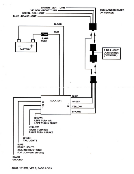
(Update, April 2016: Electrical Connection no longer seems to have the instructions for its isolator posted on line.) I scanned in the relevant page of the paper instructions that were included with Electrical Connection's isolator, and put it up as a this single-page PDF document. This is what it looks like, if you don't want to open it there:
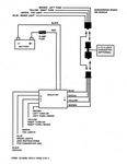
As I mentioned, the "IN" side goes to the harness; the harness wires, in turn, go to the stock wires that will serve as relay triggers. The "OUT" side are the wires that will be used to power the LEDs in the new mirrors.
THE MIRROR CIRCUITS:
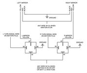
Here's the relevant paragraph from Rivco's instructions that includes the wiring connections:
4. Route the mirror wires with the other wires and cables thru any retaining clips or ties to the turn signal wire connectors (usually inside the headlight shell) leaving enough slack for the handlebars to turn full left and right without pulling on the wires. On motorcycles that have bullet type wire connectors for the turn signals the connection can be made as follows: Strip back the mirror wires about ½' [they mean ½"], unplug the bullet connector, place the striped wire inside the female bullet then plug the male into the female. On other motorcycles you may want to use 3-way crimp on splice connectors. Connect the Black wires to ground. Connect the Yellow wires to the left & right turn signals. Connect the Red wire to the running lights. If your bike does not have running lights you may connect the Red wires to any wire that has power when the ignition is turned on. This will allow the forward facing amber lights to remain on continuously yet still flash as a turn signal when activated.
WIRING THE MIRRORS AND THE ISOLATOR:
On the bike, we'll start with the right turn signal wires.
But first, a note about left and right. These refer to the sides of the bike as you're sitting on it. It doesn't matter if you're looking from the front of the bike toward the back, the side of the bike, the back of the bike, or standing on your head: the throttle grip, for instance, is on the right side of the bike (and the clutch is on the left, unless you're riding a scooter, in which case the rear brake is there). So, even though you'll see these wires on the left side of a full-frontal photo of all the wiring, we're still talking about the right side of the bike and the right turn signal.
All right, the right turn signal hookup:
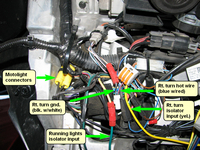
Notes about this right turn signal photo:
-
I've labeled the Motolight wires just so you know what those Posi-Locks are. They used to end in a stock connector for optional fog or driving lights; ignore those.
-
The red Posi-Lock on the black-and-white ground wire is unnecessary. Remember, I had tapped into this wire, when I thought I could merely use existing circuits for the mirror turn signals (and so had split that ground, for a three-way Wago connector).
-
The Wago connector has the cut blue-and-red hot wire for the stock turn signal as two of its inputs, although you can't see one of them. The third connection is for the yellow trigger input wire of the isolator.
-
The other red Posi-Lock, in the bottom middle, connects a yellow-and-red stock wire to the green running lights isolator input. This wire used to terminate (along with a black ground wire, which you can see wire-tied to it, higher up, at the bend) in a connector for, I believe, the unused (on my bike) stock halogen light; since this is only a trigger input, you can use any old wire that's hot only when the ignition is on.
If you want to study this picture in full size, sans labels, click here. In most browsers, after the picture finishes loading, just click anywhere on it to expand it to full size; then, use the browser's horizontal and vertical scroll bars to move around.
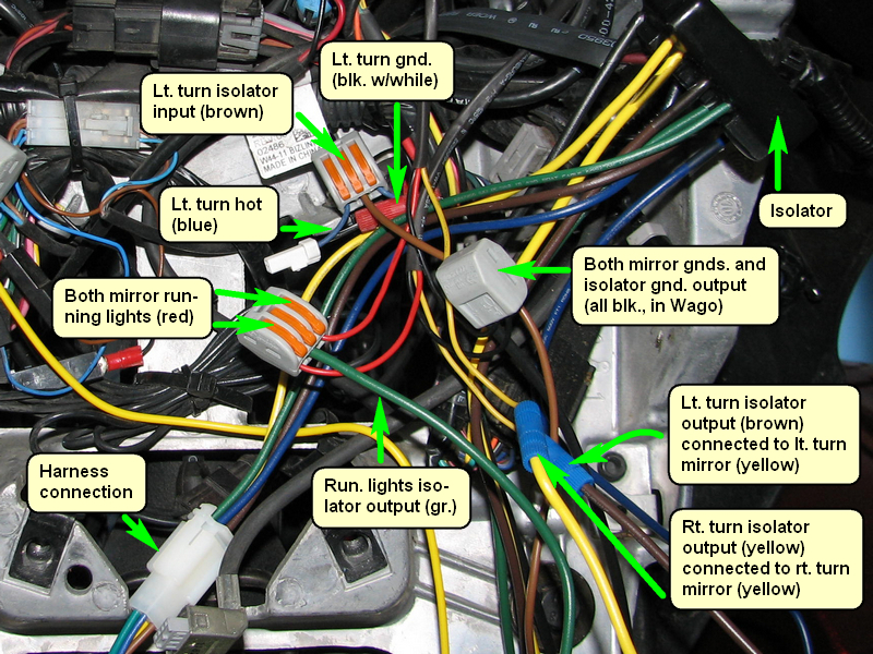
Now, the left turn signal and isolator wires:
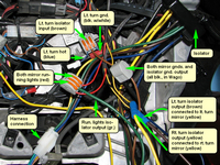
Notes about this left turn signal photo:
-
The red Posi-Lock on the black-and-white ground wire is on the unnecessarily cut wire.
-
A single Wago connector has the black ground wires from each mirror, along with the isolator output black ground wire.
-
Similarly, another Wago connector has the red running light wires from each mirror, along with the isolator output green "tail lights" (i.e., running lights) wire.
-
The blue ("brake lights") isolator and harness wires are not used; put some heat-shrink tubing over their ends, shrink it, and bundle them up with the other wires.
If you want to study this picture in full size, sans labels, click here.
Left, right, and center:
When you've finished with the in-fairing wiring — the mirrors, the isolator, the harness, the stock hot-wire triggers — this is what you wind up with:
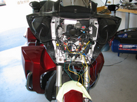
(And here's that image in full size on a separate page.)
Oops, you should probably use a few dozen wire ties to bundle up and tuck in all that wire:
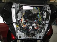
(And here's that image in full size on a separate page.)
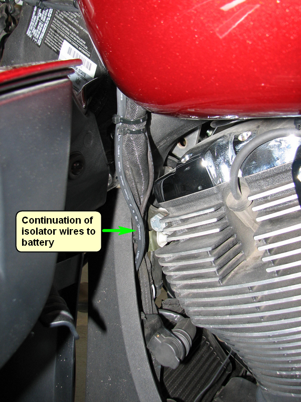
WIRING TO THE BATTERY:
We have one last task to perform: connecting the isolator to the battery, so that it can power (using its output wires) the new LEDs.
Note in the photo above that the isolator has been tucked far back into the fairing, on the left side, opposite the radio (and behind a horn I've added — see the series of pictures beginning here, if you're interested in that modification). The isolator has thick red and black wires, and they're just long enough to make it down to the battery area behind the "chin" cover on the Cross bikes. Of course, if you want to add some more wire to lengthen these, just make sure you use nice thick wire like the existing ones (using some large-size Posi-Locks, for instance).
I also enclosed most of the run of this red-and-black pair in 3/8" heat-shrink tubing, and heated and shrank the tubing; when you do this, make sure you aim your heat gun away from the isolator body. This protects the run, but is mostly for cosmetic purposes. I then ran it out the back of the fairing and down the left side of the bike:
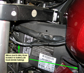
If you go down the left side of the bike, the wire run is less visible when the bike's on the side stand. Also, there's already a wire bundle there that you can wire-tie onto.
CAUTION!
When adding wire runs like this, make sure that:
-
You leave enough slack in your wiring, after adding wire-ties, that the wire is not stretched when turning the handlebars lock-to-lock.
-
Make sure the wires are not pinched, especially at full lock, by the fork tubes or any part of the triple tree.
-
When working with the battery itself, make sure you disconnect the ground side (negative terminal, black wire) first, then the hot (positive, red wire) side. When reconnecting, reconnect the red side first, then the black side. (I slip a big piece of unheated shrink wrap over the big ground wire end after disconnection, to prevent its touching the battery terminal.) The main purpose of this process is to prevent a massive, tool-welding, sparks-flying, short circuit if your screwdriver, wrench, or ratchet were to touch the frame when you're working with the positive terminal, if the ground terminal were still connected.
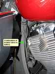
The battery is at the bottom front of the bike, below the oil cooler, behind the chin fairing. That piece is held in place by four 4mm bolts, two at the top and two underneath the bike. Remove the bolts, slide the chin toward the left side of the bike (such that a lip on its edge clears the frame), and pull it out.
Connecting to the terminals:
You'll first need to add the supplied ring terminals to the red and black isolator leads. If you don't have ratcheting crimpers, now is the time to get them.
If this is your only addition to the battery, go ahead and add the wires to the battery bolts, keeping in mind that the red wire goes to the positive terminal and the black wire goes to the negative one.
In this case — you're not using some other connection device, such as the Termin-8 or a fuse panel (read on) — you'll need to cut the supplied in-line fuse-holder wire, attach the ring terminal to one end of that instead; then, attach the other end of this fuse wire to the isolator's red wire. (This is what that butt connector is for, the one shown supplied with the isolator; if you're not an experienced crimper, just use a large Posi-Lock, instead.)
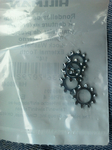
Now is also a good time to add some toothed washers to these bolts, as recommended on assorted Internet forums; loose connections here lead to all manner of problems. (Also, the torque spec listed in the Victory shop manual is way too low; the proper value is "very tight.") Here are some I picked up at Lowes:
In my case, however, I already had three extra ring terminal pairs on those battery bolts: one to power my Stebel Nautilus air horn, and two for added Powerlet sockets. You can add only so many ring terminals to the battery bolts before you run out of threads or risk questionable contacts, and I was already pushing it.
To deal with that situation, I added Powerlet's Termin-8:
The Termin-8 has beefy 12-gauge wires that connect to the battery bolts via pre-installed ring terminals (not "U" terminals, as currently shown on Powerlet's site). The red wire has an in-line fuse inside a weather-resistant case, and both wires terminate with four available screws on metal blocks; the screws on the blocks are located one to a side, at staggered heights, so there's ample room to add each connector. You connect your devices to these blocks, without glomming up the battery terminal bolts (and then slip the included flexible insulator covers over them, and wire-tie in place).
There are, of course, products similar to the Termin-8, i.e., devices that attach directly to the battery terminals, and then allow you to attach your added devices to them, instead of to the terminals. Two such examples are the Eastern Beaver 3 Circuit Solution and Kuryakyn Accessory Fused Terminal. Like the Termin-8, these are essentially fused terminal extensions; on the other hand, fuse panels (see below) are designed to be triggered by a relay, and are generally larger, more sophistacated, and more difficult to install. If you have just three or four electrical devices to add — and especially if they all need to be powered whether or not the bike's ignition is on — then a simple, fused, terminal-extension device is probably the best way to go; among those, the Termin-8 is the easiest to work with.
Fuse Panels?:
Another approach, of course, to over-booked terminals would be to add a fuse panel. This is a device with multiple pairs of connection points — typically six or eight — for you to hook up added accessories; each hot side has its own fuse. The device is connected directly to the battery, and generally includes a single relay; the relay is triggered by some existing on-bike wire that is hot only when the ignition's on. This way, those connection points are also only hot when the bike's on, although almost all of these have provision for one or more always-on circuits. This way, you can add, say, extra lights that go off when the key is turned off, and maybe an alarm system that is always hot.
I have nothing against these. In fact, I had fuse blocks on both my Valkyrie and Burgman. However, on the Victory I already had a relay and wiring harness for my horn circuit, and I wanted the two Powerlet circuits to be always hot (because if these were disabled when the bike is off, you couldn't use them to hook up a smart charger, to keep the battery in tip-top shape). So I hadn't felt the need (at least up until now) to add a separate power device.
In any event, if you want to use a fuse block, that's certainly fine. Here are some for your consideration:
If you do use a fuse panel, if you can fit it under the right side panel (where the OEM fuses reside, too), you'll have easy access for fuse replacements. On the other hand: A) replacing fuses should be an extremely rare or non-existent event, and; B) this would mean that everything you added inside the fairing would require wire runs that have to allow slack for handlebar movement and would have to travel all the way back there, neither of which is really desirable. Ideally, you'd want to put a fuse panel in the vicinity of most of your electrical add-ons. If I ever feel I need one on the Victory, I'd probably put it in the fairing; while you have to remove a dozen bolts to get inside, I don't think I ever had to replace a fuse I had in a fuse panel.
If you put a fuse block in the vicinity of the battery (which, recall, you can get at via a mere four bolts and a 4mm Allen key), or if you just use the Termin-8, or no extra device at all, try not to block air flow to the oil cooler. The Victory gets hot enough, as it is.
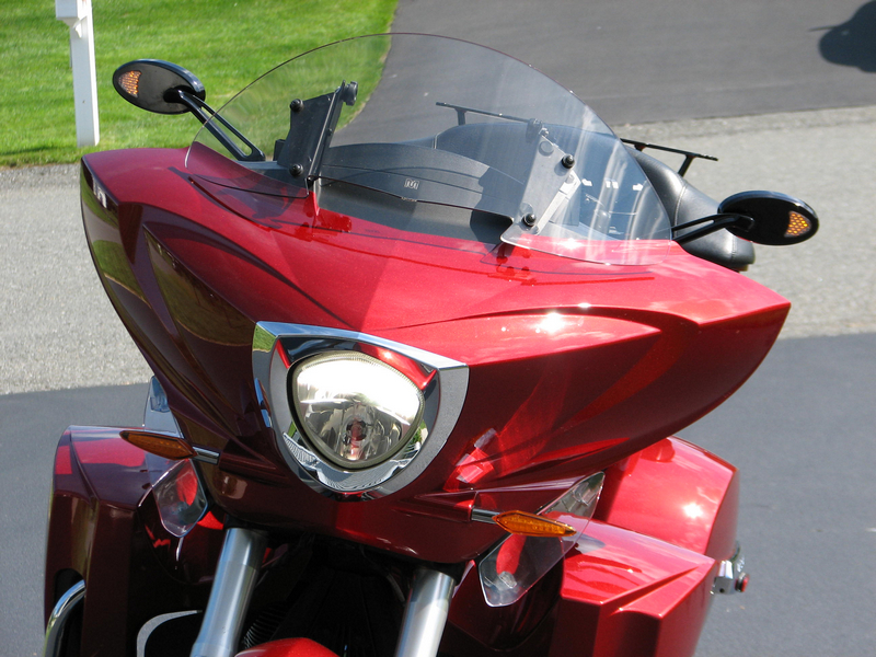
OK, ENOUGH ALREADY, HOW'D THIS ALL WORK OUT?:
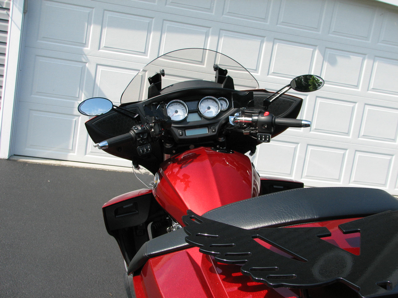
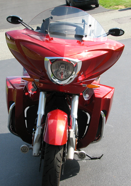
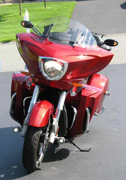
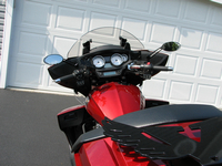
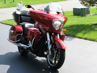
It came out great. Everything works as intended, and I think the mirrors look sharp:

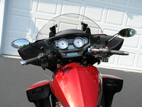
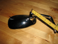
The Rivco mirrors are about the same width (5¼") as the stock mirrors, but elliptical instead of whatever you want to call the shape of the stockers. This gives them slightly less area than the OEMs (and while I could calculate the area of an ellipse, the stock pattern is just too much for me):
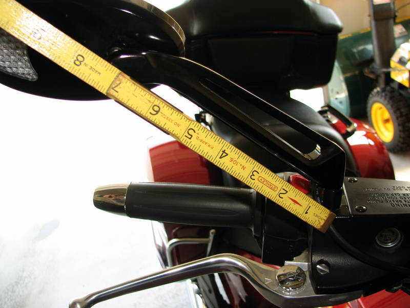
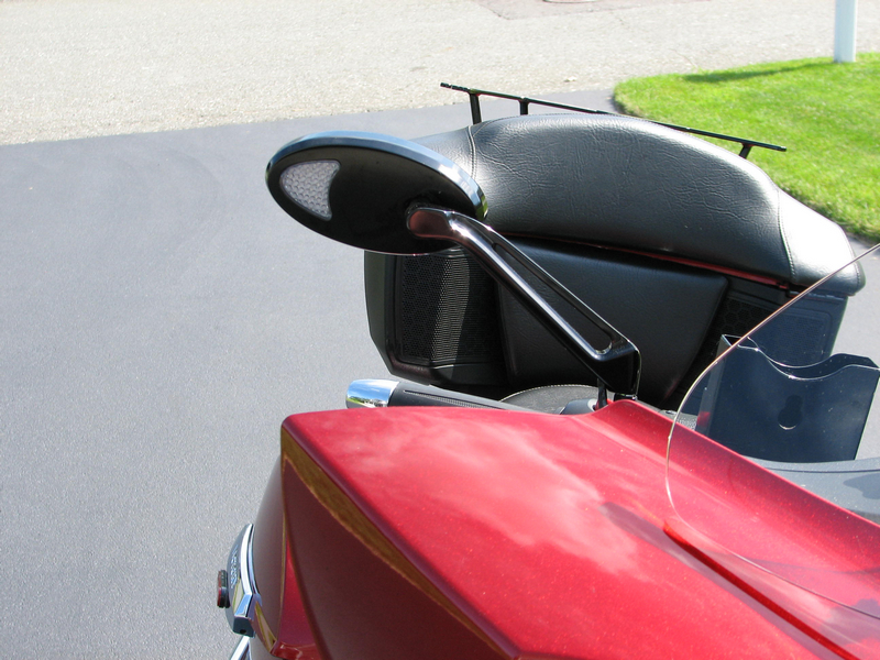
On the other hand, the Rivco mirrors stick out farther to the sides (unless you angle them way back, in which case they'll show your elbows). The handlebar mount to the center of the housing ball-and-socket area on the stockers is almost exactly 5", while that distance on the Rivcos is about 7 1/8". Let's see, assuming about a 45° stalk angle, and using the Pythagorean Theorem, means that the sideways difference is about 1½":

This makes a difference — not to discourage head-checks, mind you, but you can actually see better with these. On the other hand, I suppose this makes them more vulnerable in a tip-over, too, if you want to worry about such things.
Also, the stock mirrors would vibrate slightly in response to certain engine RPMs, each side having its own (i.e., different) resonant frequencies. The Rivco mirrors seem immune to this stock steady-cruising quirk; getting on the gas with a big V-twin, however, will still blur any mirror.
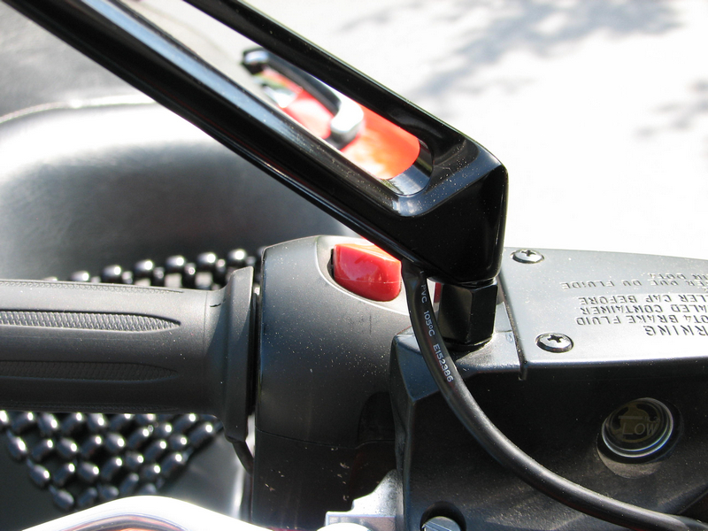
Here are a couple of shots of the adapter area on the right side — remember that business with the washers in the mount recess? — and one on the left:
Black vs. chrome?:
A highly personal decision. In my case, I went through my chrome period in seven years with my Valkyrie. If you haven't already, go ahead, click that, and check it out. I'll wait.
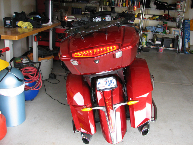
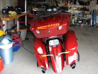
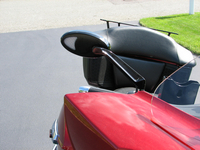
Aside from having blinged out the Valk and even not owning a blacked-out version of the Cross Country (and Victory doesn't make a blacked-out Tour version), I find that's there's plenty of black to match up with: the lowers (flaps and doors), the dash, the switch housings, the grips, the seat, and the passenger backrest. That's why I went with a black trunk rack, instead of a chrome version. Here's a shot that shows a bunch of black:
And what about the LEDs?:
As I said, with the trailer isolator all is well. That's the whole point of this project. It's hard to show light intensity in photos, but I'll try.
This in the garage, with all lights caught in the act of four-way flashing. Yes, the stock turn signals are on back there, but to their detriment they're closer to the outside light:
Here are some outdoor shots, with the mirror LEDs off and then on:


A FEW SUGGESTIONS FOR RIVCO:
If Rivco decides to revise the hardware, here are some changes I'd like to see:
- The mirror LEDs are bright enough — and maybe this only involves their outside casing — but a wider field of view for their maximum brightness would be nice. The front-facing amber LEDs, in particular, are very bright when viewed head on, but that brightness tapers off a bit more than I'd like as you move to the side.
-
As I mentioned much earlier, the ball-and-socket pivot area could use a set screw to set and maintain socket tension, rather than the it-takes-a-gorilla-to-move-them system now in place.
-
Speaking of that pivot, I think the circular cut-out in the flat area around it should have a slightly larger diameter, and perhaps the stem of the ball could be longer. That is, I'd like to have the capability of slightly more adjustment range in that ball-and-socket mechanism.
-
And I'd like to see that ball and stem anodized black, for the black mirrors.
All of that said, these may be as good as you can get today among LED mirrors, and I'm pleased with them.
OH, YEAH, THERE'S THE COST, ALL RIGHT:
If you haven't been paying attention, the (list) price of all of this (excluding any taxes and shipping):
-
Rivco LED mirrors: $249.95
-
Electrical Connection isolator: $69.95
-
Electrical Connection harness: $9.95
-
Total: $329.85
The satisfaction of getting all of this to work: priceless.
That's it. If you tackle this yourself, good luck. Regardless, thanks for reading this, and I welcome your comments.
Bill Pollack
June 2013
Niskayuna, NY

’s Web Site")